QO-100 Multimedia Beacon Reception with Software Frequency Stabilization
Equipment used
The receiving setup used for this experiment is intentionally quite simple:
- SDR: ADALM-Pluto with the original TCXO replaced by a 0.5 ppm TCXO, connected to the PC via USB
- Dish: Gibertini 125 cm offset dish
- LNB: an old, unmodified consumer satellite-TV LNB of unknown type
- LNB power: 12.5 V from a Siglent laboratory power supply, supplied through a bias-T
- Software: SDR Console, Spectrum Lab and AMSAT-DL HighSpeed Modem
No modification or external frequency reference is used for the LNB itself.
During my experiments with the QO-100 Multimedia Beacon, I became particularly interested in the problem of frequency stability.
The beacon, currently transmitted on 10,489.9935 MHz using 8APSK modulation at 7200 bit/s, turned out to be an excellent real-world signal for experimenting with software frequency stabilization.
What initially started as an attempt to receive and decode the multimedia beacon gradually became an experiment in compensating for the frequency drift of an ordinary LNB entirely in software.
The QO-100 Multimedia Beacon proved particularly suitable for this purpose because the effects of frequency instability can be observed directly in HS Modem synchronization, block reception and the 8APSK constellation.
The objective of this experiment therefore became:
How far can I compensate for the frequency drift of an ordinary, unmodified LNB using software DSP alone?
The main problem: LNB frequency drift
My QO-100 receiving setup uses an ordinary LNB without an external GPSDO reference.
Like most such LNBs, its local oscillator changes frequency with temperature. For normal SSB reception this is relatively easy to compensate, but a digital signal such as the 7200 bit/s 8APSK Multimedia Beacon provides a much more demanding test.
During longer tests I observed the received signal moving by several kHz.
The drift itself was generally quite smooth, but it was large enough that the reference required by HS Modem could eventually move outside the useful tuning range.
The goal was therefore not simply to tune the receiver once. I wanted to create a system capable of continuously following the drifting signal while presenting a nearly stationary signal to HS Modem.
First approach: SDR Console Geostationary Beacon stabilization
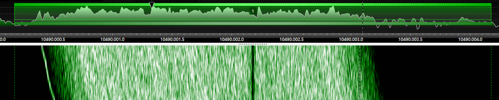
My first approach was the Geostationary Beacon stabilization in SDR Console.
This is a very useful feature for QO-100 operation because it compensates for LNB frequency drift by using one of the satellite beacons as a frequency reference.
For normal operation it works very well.
During the Multimedia Beacon experiments, however, I could still observe small movements of the reference presented to HS Modem. This made me curious whether the multimedia signal itself could be tracked directly after demodulation.
For the experimental phase I therefore disabled the SDR Console geostationary stabilization and allowed the LNB to drift naturally.
At first this sounds like a step backwards.
In practice it gave me something very useful: the uncompensated LNB could drift by several kHz, but the movement was generally smooth. This provided an excellent signal on which to experiment with an independent tracking system.

Building an AFC in Spectrum Lab
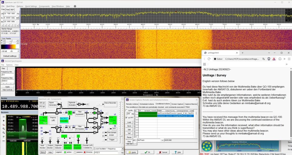
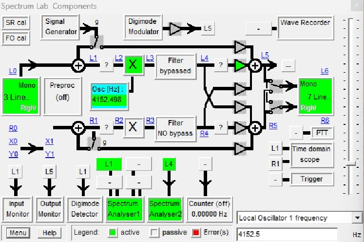
I inserted Spectrum Lab by DL4YHF between SDR Console and the AMSAT-DL HighSpeed Modem.
The experimental signal path became:
QO-100 → LNB → SDR Console → Virtual Audio Line 1 → Spectrum Lab AFC/mixer → Virtual Audio Line 2 → AMSAT-DL HS Modem
SDR Console supplies Spectrum Lab with a relatively wide audio spectrum so that several kHz of LNB movement can be accommodated.
Spectrum Lab analyses the incoming signal and continuously tracks the reference edge of the Multimedia Beacon.
Instead of continuously retuning SDR Console, I use the internal Spectrum Lab mixer as a software frequency converter.
The mixer follows the measured LNB drift and translates the complete received signal in the audio domain before passing it to HS Modem.
This means that SDR Console itself does not have to be continuously retuned by the AFC.
Tracking the reference
Several tracking methods were tested.
Simply searching for the strongest spectral component over a wide frequency range was not reliable. If another spectral component or noise became stronger, the tracker could move away from the required reference.
A much more reliable approach was to remember the previous reference position and search only within a small window around it.
After a number of experiments, the tracking expression used in Spectrum Lab became:
RefTrack=RefTrack+(peak_f(#1,RefTrack-10,RefTrack+10)-RefTrack)*0.7
Spectrum Lab therefore searches for the peak only within approximately ±10 Hz around the previously tracked position.
The difference between the newly measured position and the previous tracking position is multiplied by 0.7 before being applied.
The USB down-converter mixer is then controlled by:
circuit.osc[0].freq=RefTrack-100

The result is that the drifting reference received from SDR Console is translated to approximately 100 Hz before the signal is passed through the second virtual audio line to HS Modem.
Spectrum Lab officially provides both the peak_f() peak-frequency detector and interpreter control of the mixer oscillator, making it possible to construct this tracking arrangement without modifying SDR Console itself.
FFT and tracking update rate
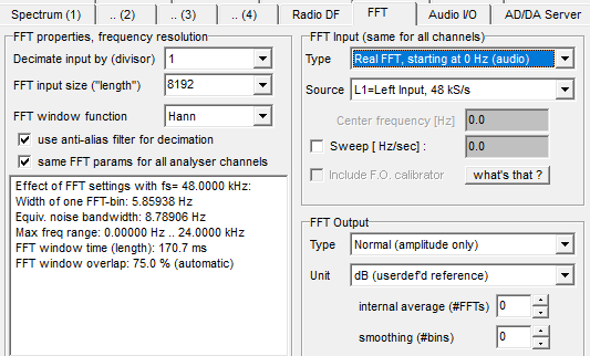
For the tracking analyser I eventually settled on:
FFT size: 8192 points
Sample rate: 48 kHz
Overlap: 75%
This produces an FFT-bin spacing of approximately:
48,000 / 8192 = 5.86 Hz
With 75% overlap, a new tracking calculation is performed approximately 23 times per second.
I also experimented with smaller FFT sizes and greater overlap.
These configurations provided faster updates, but the measured reference position became noticeably less stable.
For this particular signal, an 8192-point FFT with 75% overlap proved to be a useful compromise between frequency resolution, tracking speed and stability.
From several kHz of drift to approximately ±1 Hz tracking error
This was the most interesting result of the experiment.
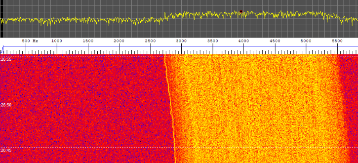
Without compensation, the received signal from the ordinary LNB could move by several kHz.
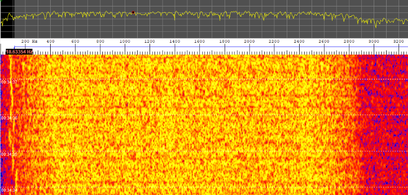
Once the Spectrum Lab tracking loop was operating, the remaining error reported by the tracking system was typically around ±1 Hz.
This value should not be interpreted as a laboratory measurement of absolute frequency accuracy.
The FFT-bin spacing in this configuration is approximately 5.86 Hz, while Spectrum Lab’s peak_f() function estimates the frequency of the spectral maximum using peak detection/interpolation.
It is therefore more accurate to describe the observed ±1 Hz as the remaining tracking error indicated by Spectrum Lab.
The important practical result was that the reference presented to HS Modem became visually almost stationary.
RX Sync also became considerably more stable.

Why use the Multimedia Beacon for this experiment?
The QO-100 Multimedia Beacon turned out to be a particularly interesting test signal for frequency-stability experiments.
With normal SSB operation, a small amount of frequency drift can easily be corrected by the operator and may have little practical importance.
The 7200 bit/s 8APSK signal provides a much more demanding test.
Frequency instability can be observed directly through:
- movement of the reference,
- HS Modem RX synchronization,
- successfully and unsuccessfully decoded blocks,
- and changes in the 8APSK constellation.
This made the beacon a very useful real-world test source for experimenting with FFT-based frequency estimation, AFC, DSP frequency translation and long-term receiver stability.
Successful live reception of the Multimedia Beacon

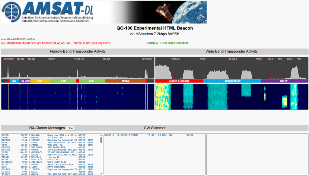
After improving the frequency tracking, HS Modem synchronization became very stable and the Multimedia Beacon data could be received continuously.
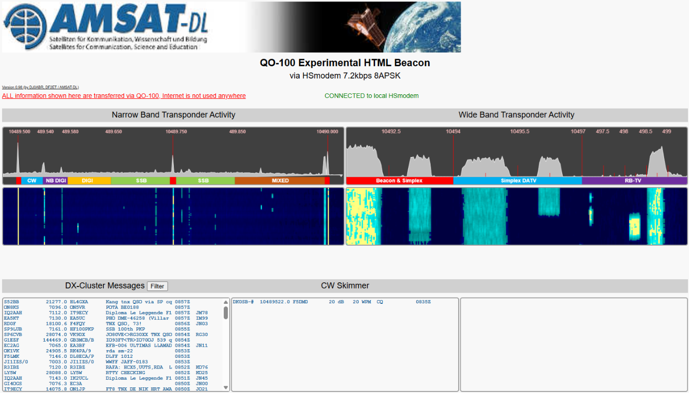
The local QO-100 Experimental HTML Beacon interface is now operational and connects directly to the running HS Modem.
The browser interface displays live information received through QO-100, including:
- Narrow Band transponder activity,
- Wide Band transponder activity,
- spectrum and waterfall information,
- DX Cluster messages,
- CW Skimmer information,
- and bulletin content.
The interface itself clearly indicates:
“CONNECTED to local HSmodem”
and the displayed information updates continuously.
This confirms that the complete live signal path is operational:
QO-100 → receiver → SDR Console → Spectrum Lab → HS Modem → local HTML interface
The browser is therefore not simply displaying a static webpage. It acts as the local user interface for information continuously received and decoded by HS Modem.
File reception and failed blocks
There is still an important distinction between successful live reception and completely error-free reception of every individual transmitted file.
HS Modem can maintain RX synchronization while occasional blocks still fail.
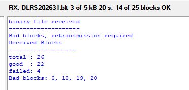
During my tests I have therefore seen .blt files appear in the receive directory even when a particular transfer was not completely successful.
For this reason, the presence of a .blt file alone should not automatically be interpreted as proof that every block belonging to that transfer was received correctly.
The reliability of individual file transfers is still being investigated.
This is also one reason why I am now performing much longer reception tests rather than evaluating the system from only a few minutes of reception.
Looking at the 8APSK constellation

Another interesting observation came from the HS Modem constellation display.
During good reception periods, the 8APSK constellation shows clearly recognizable symbol groups.
At other moments these groups become considerably more dispersed, and these periods can correspond with unsuccessful blocks.
The exact cause has not yet been established.
Possible factors include signal-to-noise ratio, LNB phase noise, short-term variations elsewhere in the receiving chain, timing recovery, or other aspects of the 8APSK demodulation.
I also experimented with phase monitoring inside Spectrum Lab.
However, measuring a useful carrier-phase error directly from an 8APSK data signal is not straightforward because the modulation itself intentionally changes phase.
A proper carrier-recovery system would be required before such a measurement could be interpreted as a phase error suitable for correction.
For this reason I decided not to add another experimental phase-correction loop.
The frequency-tracking experiment already provides a substantial improvement and can be evaluated independently.
Short-term experiments versus long-term reception
There are actually two slightly different operating conditions in this experiment.
For the original AFC experiments, I intentionally disabled SDR Console Geostationary Beacon stabilization.
This allowed the LNB to drift freely and made it possible to observe how well the Spectrum Lab tracker could follow several kHz of movement.
For long-term reception, however, there is a practical limitation.
Eventually the accumulated LNB drift can become large enough that the Multimedia Beacon moves outside the audio bandwidth being supplied by SDR Console to Spectrum Lab.
Spectrum Lab cannot track a signal which is no longer present at its input.
For long-duration reception I therefore use a combined approach:
SDR Console Geostationary Beacon stabilization → Spectrum Lab fine AFC → HS Modem
In this configuration the two systems perform different jobs.
SDR Console provides the coarse long-term stabilization, keeping the received signal inside the required passband.
Spectrum Lab then performs fine tracking directly on the Multimedia Beacon reference before the signal reaches HS Modem.
This combined configuration is currently being evaluated during extended reception periods.
No modification of the LNB
One aspect of the experiment that I find particularly interesting is that the LNB itself remains completely unmodified.
An externally referenced or GPS-disciplined LNB would of course provide much better inherent frequency stability and is an excellent technical solution for QO-100.
But that was not the purpose of this experiment.
The question was:
How much of the frequency instability of an ordinary LNB can be compensated in software?
Instead of making the LNB itself more stable, the experimental system measures its movement and compensates for that movement later in the DSP chain.
The short-term experimental receiving chain is therefore:
QO-100 Multimedia Beacon → standard LNB → SDR Console → Virtual Audio Line 1 → Spectrum Lab AFC/mixer → Virtual Audio Line 2 → AMSAT-DL HighSpeed Modem
For long-term reception I additionally enable SDR Console’s Geostationary Beacon stabilization to prevent the accumulated LNB drift from moving the signal outside the available audio bandwidth.
Current results
At the present stage of the experiment:
The QO-100 Multimedia Beacon is being received and decoded.
The local HTML interface operates continuously and displays live data received through HS Modem.
The Spectrum Lab AFC can follow several kHz of natural LNB drift, while the remaining tracking error indicated by Spectrum Lab is typically around ±1 Hz.
RX synchronization is now very stable.
Individual blocks can still occasionally fail, so the reliability of complete file transfers and the behaviour of the 8APSK constellation remain subjects for further investigation.
The most important result, however, is that the frequency-stabilization experiment works well enough to separate the large LNB drift problem from the remaining demodulation issues.
Conclusion
What started as an attempt to receive the QO-100 Multimedia Beacon became a useful experiment in software frequency stabilization.
The Multimedia Beacon proved to be an excellent real-world test signal because it immediately exposes problems which are much less obvious during ordinary SSB reception.
By tracking the beacon reference in Spectrum Lab and dynamically controlling its internal frequency converter, several kHz of natural LNB drift can be compensated without modifying the LNB itself.
For the original experiment the LNB was deliberately allowed to drift freely, demonstrating the capability of the Spectrum Lab tracking loop.
For long-term reception, SDR Console Geostationary Beacon stabilization can be added as a coarse correction, while Spectrum Lab performs the fine tracking before the signal reaches HS Modem.
The experiment is not finished.
Long-term reception, complete file-transfer reliability and the behaviour of the 8APSK constellation will continue to be investigated.
But the main objective has already been demonstrated:
A standard LNB with significant frequency drift can be used as a practical platform for experimenting with software-based frequency stabilization of the QO-100 Multimedia Beacon.
More results and screenshots will be added as the experiment continues.
73!
Software and References
AMSAT-DL QO-100 NB Transponder Bandplan — Current QO-100 narrowband transponder bandplan and operating information. The current bandplan lists the Multimedia Beacon at 10,489.9935 MHz using 8APSK at 7200 bit/s.
AMSAT-DL QO-100 NB Transponder Bandplan
AMSAT-DL / DJ0ABR HighSpeed Multimedia Modem (HS Modem) — The modem software used to receive and decode the QO-100 Multimedia Beacon.
DJ0ABR SSB HighSpeed Modem source repository
AMSAT-DL Satellite Wiki — QO-100 Multimedia Beacon — Documentation covering the Multimedia Beacon, HS Modem reception, streaming operation and the local HTML interface. Some older documentation may contain historical experimental frequencies, so the current AMSAT-DL bandplan should be used for the present beacon frequency.
QO-100 Multimedia Beacon documentation
AMSAT-DL HS Modem Technical Specification — Technical information about the HighSpeed Modem, supported modulation modes, data rates and transmission system.
HS Modem Technical Specification
Spectrum Lab by DL4YHF — Used as the DSP stage between SDR Console and HS Modem.
Spectrum Lab Circuit Components and Mixer Documentation — Documentation for the internal frequency converter and oscillator. Spectrum Lab provides interpreter access to the oscillator through circuit.osc[0].freq.
Spectrum Lab Circuit Components documentation
Spectrum Lab Interpreter — Documentation for the interpreter and the peak_f() function used for reference-frequency detection. Spectrum Lab documents peak_f() as returning the frequency of the strongest peak within the specified range and notes that its accuracy depends on the FFT configuration.
Spectrum Lab Interpreter documentation
SDR Console — Used as the SDR receiver and audio source. Its Geostationary Beacon stabilization is also used for coarse long-term stabilization during extended tests.